

The geodetic infrastructure managed by the Italian Geodetic Observatory in Antarctica (IGOA) is presented below.
GNSS Stations
Continuous GNSS Stations
TNB1 and TNB2
In Terra Nova Bay (TNB), near the Italian seasonal scientific base Mario Zucchelli Station (MZS), there are two continuous GNSS stations managed by the IGOA and called TNB1 and TNB2. The data collected by these stations (whose coordinates are listed in Table 1) are sent daily to Italy, and are available for download (in RINEX format) from the dedicated page of this website.
| Station | TNB1 | TNB2 |
| Reference Frame | ITRF2000 epoch 2003.0 | ITRF2000 epoch 2003.0 |
| Latitude | 74° 41′ 55.69965″ S | 74° 41′ 56.14134″ S |
| Longitude | 164° 06′ 10.58957″ E | 164° 06′ 10.11967″ E |
| Ellipsoidal height | 72.27 m | 71.071 m |
TNB1 continuous GPS station was monumented during the 1997-1998 campaign on a granite outcrop. It was originally equipped with an Ashtech Z-12 GPS receiver and an Ashtech 700936D Dorne Margolin antenna with choke ring. Installed on a concrete pillar, TNB1 continuously collected data from the GPS constellation for about 17 years until November 2015, when the instrumentation was completely renewed. Currently, the station is equipped with a Leica GS25 GNSS receiver and a Leica AT504 Dorne Margolin choke ring antenna. TNB1 collects data from GPS and GLONASS constellations in accordance with the specifications described in Table 2.
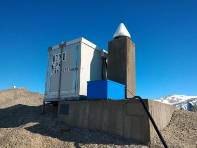
with the old instrumentation
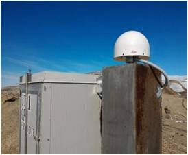
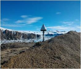
TNB2 continuous GNSS station was monumented during the 2007-2008 campaign on a granite outcrop, a few metres from TNB1. Equipped with a Topcon GB1000 GNSS receiver and a Topcon CR-G3 choke ring antenna installed on a steel pillar, TNB2 collects data from GPS and GLONASS constellations in accordance with the specifications described in Table 2.
| Session Length | 24h |
| Acquisition Rate | 15s |
| Elevation Angle | 3° |
VL01, VL12, and VL30
In 2014, thanks to a collaboration with UNAVCO (University Navstar Consortium) in the context of POLENET (Polar Earth Observing Network) – ANET (Antarctica NETwork monitoring) project, three sites of the Victoria Land Network for Deformation Control (VLNDEF) were equipped with permanent GNSS stations: VL01 in Tombstone Hills, VL12 in Monte Cassino, and VL30 in South Mount Bruce. The stations (whose coordinates are listed in Table 3) are part of the POLENET permanent GNSS network, and the collected data are freely accessible on the UNAVCO website, where their operational status can also be monitored in real time.
| Station | VL01 | VL12 | VL30 |
| Reference Frame | ITRF2000 epoch 2003.0 | ITRF2000 epoch 2003.0 | ITRF2000 epoch 2003.0 |
| Latitude | 72° 27′ 00.49337″ S | 72° 16′ 27.98421″ S | 70° 35′ 55.39560″ S |
| Longitude | 169° 43′ 30.25310″ E | 169° 43′ 37.19134″ E | 162° 31′ 30.51127″ E |
| Ellipsoidal height | 596.919 m | 1932.975 m | 1491.517 m |
The three stations are mounted on granite outcrops, and a system of solar panels and backup batteries powers each continuously throughout the whole year. The instrumentation consists of Trimble NETRS GPS receivers and TRM59800.00 (radome SCIS) choke ring antennas installed on steel pillars. VL01, VL12, and VL30 collect data from the GPS constellation in accordance with the specifications described in Table 4.
A satellite transmission system makes the data acquired by VL01 and VL30 available for download from the UNAVCO website in real time, while the data collected by VL12 (due to a malfunction in the satellite transmission) are currently available only starting in March of the year following the year of acquisition.
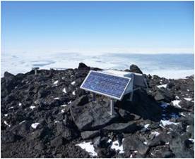
at Tombstone Hills
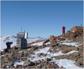
at Monte Cassino
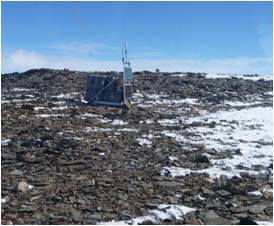
at South Mount Bruce
| Session Length | 24h |
| Acquisition Rate | 30s |
| Elevation Angle | 3° |
for VL01, VL12, and VL30
INXP and LRSN
In 2016, as part of the MALOX (MAss LOss in wind fluX) project in collaboration with the Laboratory for Earth and Climate Observation and Analysis of ENEA’s Department for Sustainability (Dipartimento Sostenibilità, Circolarità e Adattamento al Cambiamento Climatico dei Sistemi Produttivi e Territoriali – SSPT), two new permanent GNSS stations were established at remote sites: INXP at Inexpressible Island and LRSN on Mount Larsen. While LRSN was established on a granite outcrop, due to MALOX project requirements, it was not possible to install INXP on a rocky outcrop.
| Station | INXP | LRSN |
| Reference Frame | WGS84 | WGS84 |
| Latitude | 74° 56′ 55.1″ S | 74° 57′ 02.0″ S |
| Longitude | 163° 41′ 06.3″ E | 161° 46′ 10.1″ E |
| Ellipsoidal height | 32 m | 948 m |
INXP and LRSN stations are equipped with Topcon Net-G3 GNSS receivers and Topcon CR-G5 (radome TPSH) antennas, installed on steel pillars, and collect data from the GPS and GLONASS constellations with specifications described in Table 6. Since there is no satellite communications device, the collected data needs to be manually retrieved by IGOA operators during the Austral summer campaigns. For this reason, the data are available for download (in RINEX format) at the dedicated page of this website, starting from March of the year following the year of logging.
Each station is powered by a system of solar panels, wind turbines, and backup batteries that enables continuous operation throughout the whole year. Both stations are equipped with Topcon Net-G3 GNSS receivers and Topcon CR-G5 choke ring antennas (TPSH radome) mounted on steel pillars. INXP and LRSN collect data from the GPS and GLONASS constellations in accordance with the specifications described in Table 6.
Since there is no satellite communication device, IGOA operators must manually retrieve the acquired data during summer expeditions. For this reason, the data are available for download (in RINEX format) on the dedicated page of this website only starting in March of the year following the year of acquisition.
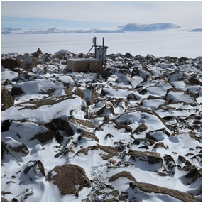
at Inexpressible Island
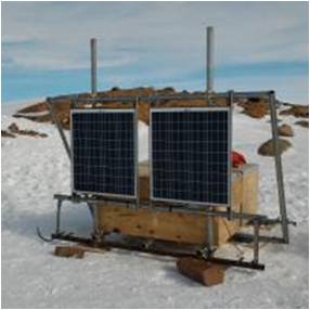
at Monte Larsen
| Session Length | 24h |
| Acquisition Rate | 30s |
| Elevation Degree | 3° |
for INXP and LRSN
Seasonal GNSS Stations
VL05 and VL18
In 2008, permanent stations were monumented at two remote sites of the Victoria Land Network for DEFormation control (VLNDEF) vertices: VL05 at Cape Phillips and VL18 at Starr Nunatak. The stations’ coordinates are listed in Table 7.
| Station | VL05 | VL18 |
| Reference Frame | ITRF2000 epoch 2003.0 | ITRF2000 epoch 2003.0 |
| Latitude | 73° 03′ 47.05152″ S | 75° 53′ 54.71732″ S |
| Longitude | 169° 36′ 43.87748″ E | 162° 35′ 37.36182″ E |
| Ellipsoidal height | 478.493 m | 58.011 m |
VL05 and VL18 stations are monumented on granite outcrops and equipped with Topcon GB-1000 GNSS receivers and Topcon CR-G3 choke ring antennas, installed on steel pillars. The stations collect data from the GPS and GLONASS constellations (data specifications are described in Table 8).
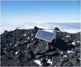
at Cape Phillips
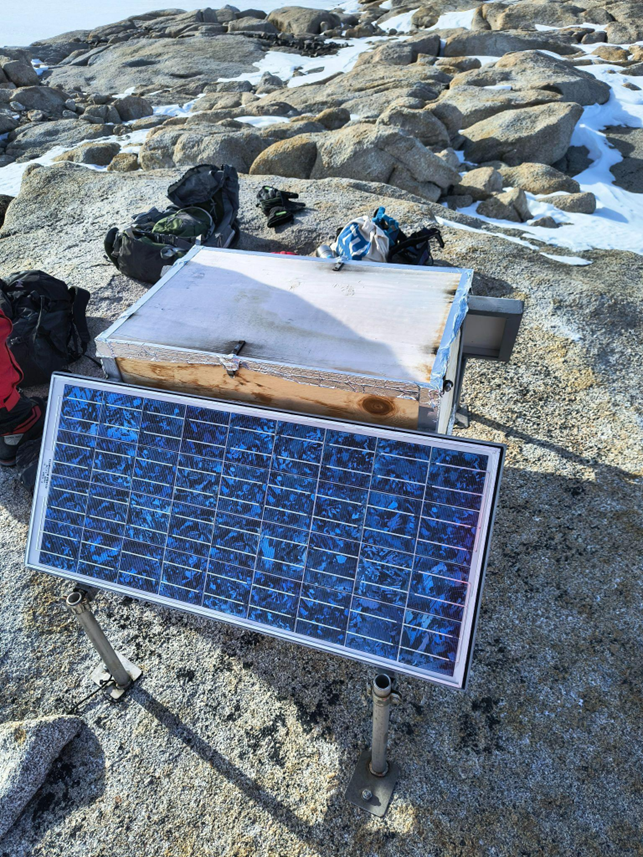
at Starr Nunatak
| Session Length | 24h |
| Acquisition Rate | 15s |
| Elevation Degree | 3° |
for VL05 and VL18
Solar panels and a set of backup batteries power the stations from the end of October (opening of MZS) until the end of March, when winter arrives, and the polar darkness interrupts the power supply. Due to the absence of satellite communication devices, the data collected during this period cannot be transmitted remotely, and IGOA personnel have to manually retrieve it during summer expeditions, at which time the stations’ electrical power is also manually rebooted. For this reason, the data are made available for download (in RINEX) format on the dedicated page of this website, starting from March of the year following the year of logging.
Episodic GNSS Stations
Victoria Land Network for DEFormation control (VLNDEF)
The Victoria Land Network for Deformation control (VLNDEF) was established between 1999 and 2001 in the framework of the SCAR GIANT (Geodetic Infrastructure of Antarctica) program. The project was funded by the PNRA and realized by the IGOA under the supervision of the SCAR ANTEC (Antarctic Neo-TECtonics) group and in collaboration with the international POLENET consortium.
The network was conceived to investigate the distinctive geological and tectonic setting of Northern Victoria Land (NVL), which is characterized by a Cenozoic fault framework with right-lateral strike-slip kinematics. The distribution of the stations was carefully planned by using geological and tectonic maps to balance site accessibility with proximity to fault lines and rocky outcrops. The chosen sites (whose location is shown in Figure 11) are located across an area extending over 500 km in the North–South direction and 300 km East–West direction.
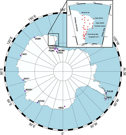
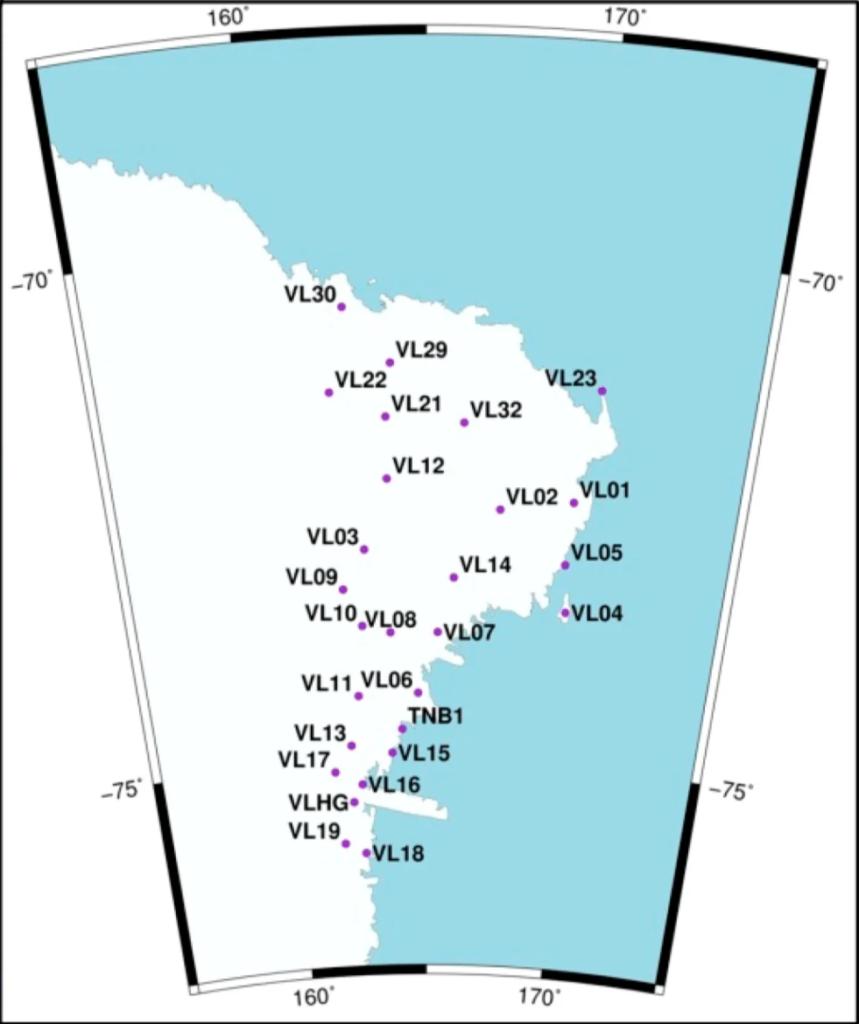
Fig. 11 – On the left, an overview of the location of GNSS Antarctic stations from the POLENET network and the VLNDEF network is represented in the upper-right insert (after Zanutta et al., 2017). On the right, a zoom on the VLNDEF and its stations’ location (after Zanutta et al., 2018).
The nearly 30 vertices of the network were monumented using vertical stainless-steel cylinders anchored directly into bedrock, with GNSS antennas mounted on top of the cylinders without any additional adaptors. The sites have been surveyed multiple times to date, through campaigns performed by the IGOA personnel during the Austral summer expeditions.
Data collected from the VLNDEF have enabled the estimation of relative residual intra-plate velocities, providing insights into the present-day kinematics of Northern Victoria Land and contributing to deepen the understanding of the region’s neotectonic processes and geophysical phenomena.
Tide Gauge
Among the activities carried out by the Observatory is the collection of tide gauge data using a pressure sensor installed on the seabed off the coast of the Mario Zucchelli Station (MZS) in Terra Nova Bay. These observations have been ongoing since 1998, the year the Observatory was founded, and the tide gauge was first installed. The IGOA tide gauge is part of a network of tide gauges located along the Antarctic continental coast at various research stations.
During the XXXVI Expedition (2020-2021), the instrumentation was upgraded. The instrument currently in use is the SeaGuard Recording Current Meter manufactured by AANDERAA (Fig. 12). The sensor, installed at a depth of 27 meters at the coordinates listed in Table 9, measures hydrostatic pressure at the installation depth, acquires data every 15 minutes, and stores it on an SD card. During each expedition, with the support of MZS’s diving teams, the tide gauge is retrieved, undergoes routine maintenance (battery replacement, lubrication of O-rings, etc.), and is returned to its installation site. At the same time, IGOA staff also download the data from the SD card for post-processing and analysis. For this reason, the data is available for download on the dedicated page of this website starting in March of the year following the year of acquisition.
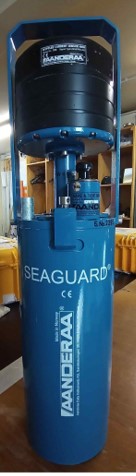
| Latitude | 74° 41’ 30.10468” S |
| Longitude | 164° 07’ 00.59402” E |
| Ellissoidic Height | -54.12 m |
The collected data help define the absolute altimetric geoid model, both globally and locally. To do this, the sensor’s pressure measurements – after being corrected for the effects of atmospheric pressure, tides, and wave motion – are compared with the ellipsoidal heights determined via GNSS, thereby allowing the geoid’s undulation to be derived. Furthermore, tide gauge data enable the development of high-precision ocean tide models, which are useful not only for their intrinsic scientific value but also for studying correlations with environmental and climatic phenomena.